How the ECU Processes Sensor Signals in Real Time
Hundreds of sensors, several thousand calculations per second, microsecond-accurate actuator control — what actually happens inside the engine control unit.
May 6, 2026 by Leo Efimow
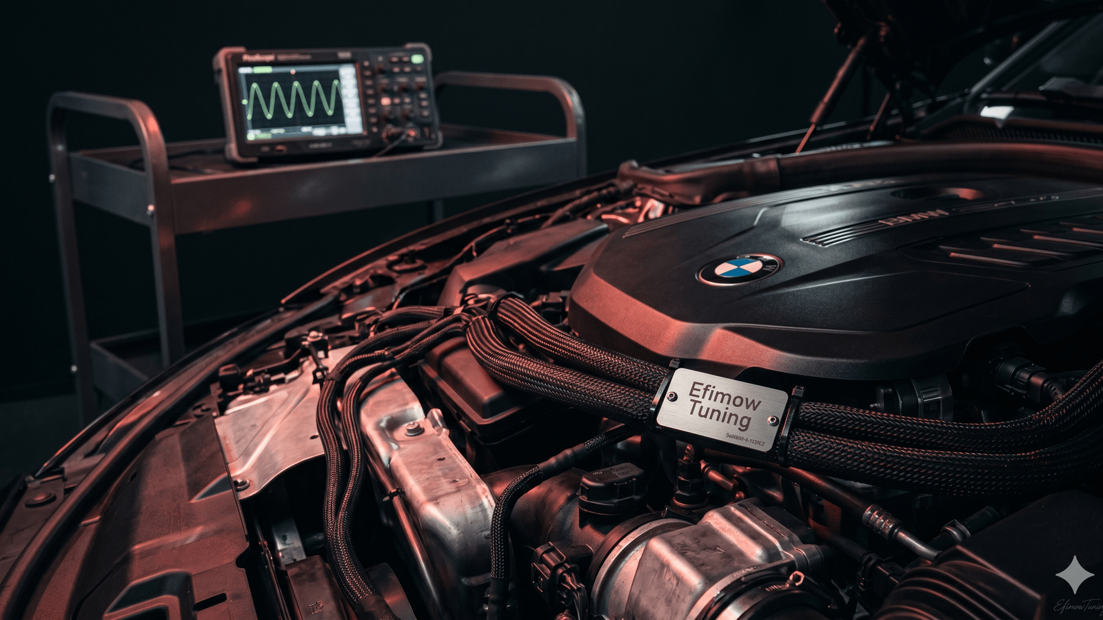
From the outside, a modern BMW DME looks unremarkable — a flat aluminum housing with two or three connectors. Inside that box, however, sits one of the densest real-time workloads in the car. Hundreds of sensor inputs are sampled in parallel, several thousand calculations run per second, and at the end of the chain, injectors open for microsecond intervals while spark plugs fire at a precise crankshaft angle. The whole process is surprisingly approachable once you walk it cleanly from sensor to actuator.
The input side: what the ECU actually measures
The engine control unit (ECU) takes its information from two worlds: from sensors mounted on the engine itself, and from data on other control units arriving over CAN and FlexRay buses. On a current BMW B48 four-cylinder, the engine-mounted sensors fall into roughly four groups.
Position and speed come from the crankshaft sensor — an inductive or Hall-effect pickup that tracks the teeth on the trigger wheel. From its signal, the ECU reconstructs both engine speed and the exact rotational position of the crankshaft. Two camshaft sensors complement it, reporting intake and exhaust cam position — essential for variable valve timing (VANOS) and for cylinder identification at start-up.
Load detection on the B48 is done primarily through a combined MAP sensor (manifold absolute pressure), which integrates intake-manifold pressure and intake-air temperature into a single device. On boosted variants, an additional pressure sensor sits ahead of the throttle to read boost. Old-school mass-air-flow (MAF) sensors are rare on modern BMW four-cylinders — load is computed from pressure, temperature and engine speed instead (the speed-density approach).
Combustion quality is monitored by lambda sensors before and after the catalyst (a wideband sensor up front, a switch-type sensor downstream), plus several knock sensors mounted on the block. Lambda control is a textbook closed loop: target lambda comes from a map, actual lambda comes from the sensor, and the difference is applied as a correction to injector pulse width.
Temperatures and driver inputs form the fourth group: coolant, oil, intake-air, and on some engines exhaust temperature, plus the accelerator pedal sensor with two redundant potentiometers. CAN traffic adds wheel speeds, steering angle, ambient temperature, and the torque request from the transmission control unit (TCU).
Analog signals get digitised by integrated A/D converters on the microcontroller, typically at 10- or 12-bit resolution. Fast inputs like the knock sensor and crank sensor are sampled at much higher rates than slow ones like coolant temperature — the ECU allocates its compute budget accordingly.
From measurement to actuator command: maps and interpolation
From those inputs the ECU computes what the actuators should do. The heart of that logic is the map — usually a two-dimensional table that stores a target value for each combination of engine speed and load. A worked example: at 3,000 rpm and 70 % relative load, the base injection map holds an injection-quantity value, the timing map holds a value in degrees before TDC, and the boost map holds a target manifold pressure for a turbo car.
These tables are kept small for two reasons. First, resolution is bounded — typical sizes are 16 × 16 or 20 × 16 break points. Second, the values are stored in fixed-point format because that is faster on a microcontroller than floating-point. Since the actual operating point almost never falls exactly on a break point, the ECU interpolates between the four surrounding cells, weighted by the distance from the current input to each axis. The result is a smooth response even though the underlying memory holds only a coarse grid.
On top of the base maps sit corrections: lambda trim from the oxygen sensor, knock retard from the knock sensors, altitude and temperature corrections, and adaptation values that compensate for component tolerances and wear. A modern BMW DME contains hundreds of such maps, and this is exactly where serious software tuning works: not by overriding the control loop, but by shifting the table values and the correction limits — within what the hardware can safely handle.
The actuator side and the time budget
The computed setpoints become drive signals for the actuators. Injectors are opened by their solenoid or piezo driver for a duration measured in microseconds — a direct-injection BMW typically operates between 0.3 and 4 ms per injection event. Spark plugs fire with an accuracy measured in degrees of crankshaft angle, not milliseconds, which has to be translated into microseconds depending on engine speed. Wastegate and throttle are commanded by PWM signals whose duty cycle is derived from the boost and air-mass targets.
The ECU's time budget is easy to pin down with a quick example. A four-cylinder gasoline engine at 6,000 rpm needs 200 ignition events and 200 injection events per second — one combustion every 5 ms. Each one demands a complete pre-calculation: map lookup with interpolation, corrections, torque-model cross-check, plausibility validation. On top of that sit lambda control on a 10–20 ms cadence, knock detection on every combustion, CAN traffic with the gearbox, ABS and HVAC, on-board diagnostics with their plausibility checks, and background tasks like adaptation and fault-memory housekeeping.
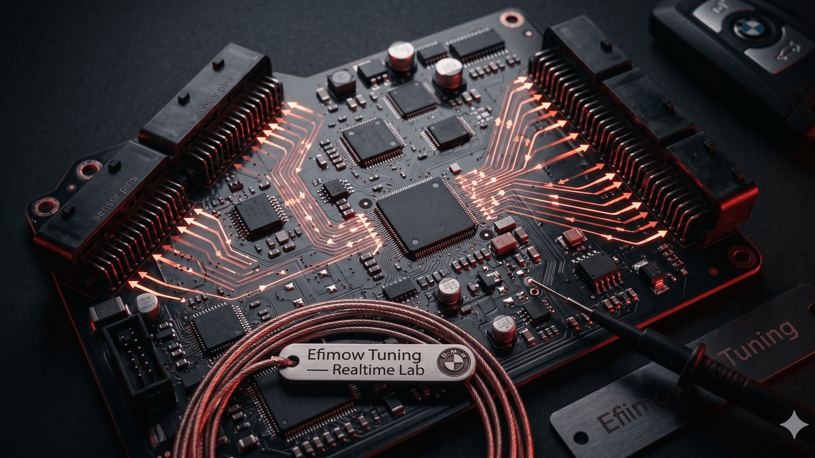
To make all of this deterministic, the ECU runs a real-time operating system (RTOS) along AUTOSAR lines. The workload is broken up into tasks, each with a fixed priority and a fixed time slot. On the hardware side, the multiple cores of the Infineon TriCore Aurix family (TC3xx at up to 300 MHz, TC4x at up to 500 MHz) keep critical tasks from being blocked by slower ones. Safety-relevant functions like torque plausibility even run redundantly on two cores in lockstep — if one drifts or fails, a fault is logged and the system drops into a safe limp-home mode.
When a knock sensor flags an anomaly, the ECU can pull ignition timing within a handful of combustions and reduce boost as needed. The same chain handles over-temperature events, lambda excursions, or a plausibility conflict between torque request and measured load. Protection logic is woven into the control loop, not bolted on top.
Bottom line
The ECU isn't a computer that occasionally decides something. It is a real-time controller watching hundreds of sensors and reacting thousands of times per second. Sensor → calculation → actuator → measurement → correction — that loop is the engine behind the engine. Once that mental model is in place, it also becomes obvious why clean tuning has nothing to do with disabling safeguards. Protection logic stays active, the control loops stay closed, and only the setpoints move. The work happens where the ECU is already deciding — inside the maps.