Inside a Tuning Box: How Sensor Signals Get Faked
A detailed technical look — which sensors are affected, how the signal is altered, and why the ECU rarely notices (yet still pays the price).
May 6, 2026 by Leo Efimow
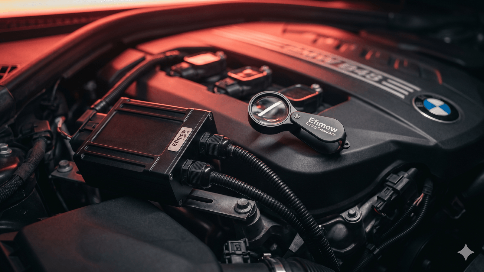
Open up a typical aftermarket tuning box and you find unspectacular hardware: a small PCB, a microcontroller the size of a grain of rice, a couple of trim resistors, and two connectors. That's all. And yet the marketing claims this little module delivers "up to 30% more power." How is that possible when nothing inside the ECU itself gets changed? The answer comes down to a single technical trick: the box manipulates an analog sensor signal on its way to the ECU and exploits the engine's own factory control loops to do the rest of the work. Let's look at how that actually plays out.
Which Sensors Are Targeted
A tuning box is always wired into one or two sensors — never all of them. Which sensors depends on the engine. On most direct-injection BMWs, three candidates are typical:
- Rail pressure sensor (common-rail diesels and FSI gasoline engines): reports the current fuel pressure in the high-pressure rail, typically 0.5-4.5 V analog
- Boost pressure / MAP sensor (turbocharged gas and diesel): measures absolute manifold pressure, typically 0.5-4.5 V analog or digital over the SENT bus
- Hot-film mass air flow sensor (HFM): reports the inducted air mass, usually as a digital frequency signal — rarely targeted because it's harder to spoof
By far the most common targets are the rail pressure sensor on diesels and the MAP sensor on turbocharged gasoline engines. Both are analog, both sit on accessible spots in the wiring harness, and both feed a closed-loop setpoint regulation inside the ECU that depends on a single sensor reading — exactly what a box exploits.
How the Signal Is Falsified — MAP Sensor Example
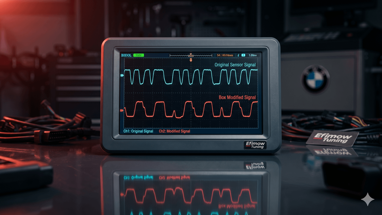
Take the MAP sensor on a B48 engine: it produces a linear voltage output, roughly 0.5 V at 0.2 bar absolute (manifold under load at low RPM) up to 4.5 V at 3.0 bar absolute (full boost). The ECU converts that voltage into a pressure value through a fixed lookup curve and compares the result with the boost target map. If actual pressure is below target, the wastegate closes further and/or the variable turbine geometry is set more aggressively.
A tuning box splices into the sensor's supply and signal lines. It reads the real voltage — say 4.2 V, corresponding to about 2.75 bar absolute — and forwards a shifted value to the ECU, for example 2.8 V. The ECU interprets 2.8 V as roughly 1.8 bar absolute and now sees a delta to setpoint of 1.0 bar. It reacts with factory logic: wastegate further closed, turbo working harder, real pressure climbs — while the "target" appears to be reached on the readback. Boxes like this typically yield an extra 0.3-0.5 bar of real boost depending on load and RPM.
Mathematically, the manipulation is a negative offset or an altered scale factor on the sensor line. Better boxes vary the offset over RPM and load so that idle and low-load operation don't drift outside the permitted range — that would trigger a fault code immediately.
Why the ECU "Doesn't Notice" — and Why It Actually Does
The ECU first checks every sensor against a plausible value range: is the signal inside min/max, is the rate of change physically possible, is the supply voltage stable? The box's outputs pass all of those checks effortlessly — they sit inside a real voltage window, just the wrong one.
Where it gets tricky is the plausibility check between multiple sensors. Modern BMW DMEs cross-reference the MAP sensor with the hot-film mass air flow plus intake air temperature — pressure, temperature, and RPM are enough to compute a theoretical air mass, and that has to match the measured value within a tolerance. The box only shifts pressure, not air mass — so the more aggressive the offset, the more the pressure-to-airmass ratio drifts. A mild offset stays inside tolerance. A strong offset, or sustained full load, tips the plausibility — fault code, possibly limp mode.
The same logic applies to the torque plausibility check: the ECU continuously calculates a modeled torque from injection quantity, lambda, and efficiency, and compares it against a measured torque derived from RPM gradient and load. If the box pushes more pressure and more fuel through but the torque model stays conservative, the discrepancy can become visible.
The Real Problem: Protections Run on Lies
This is where it gets technically delicate. The knock retard map in the ECU is a table over RPM and load. It pulls ignition timing the moment a knock event is reported — by an amount tied to the load point the ECU thinks it is seeing. When the box reports lower pressure than reality, the ECU believes it is at a lower load point — and pulls a smaller retard value from the knock map. The actual knock event happens at higher real load; the correction is calibrated for a lower entry. The result: insufficient retard, and the knock can repeat.
The same goes for the EGT protection curve and the torque limiter. Both rely on tables whose inputs depend, directly or indirectly, on the manipulated sensor reading. A box aiming for 30% more pressure leaves the protection system blind in exactly the load band where energy density is highest.
Bottom Line
A tuning box is technically elegant and conceptually brutal: it exploits the factory control loops without understanding them. It shifts a single analog sensor reading by a few hundred millivolts — and the ECU does the rest. What it does not change are the tables that decide, in a borderline situation, how the engine gets protected. Those tables keep computing on the wrong inputs. In normal load it goes unnoticed; near the knock threshold or under heat it shows up — usually with damage. Once you understand the trick, you see a tuning box differently: not as a budget tuning option, but as a piece of hardware that lies to a highly complex control system at its weakest point.